
When the switch is off, the control voltage is maximum and the light is fully bright. When the switch is on, the control voltage is near 0 and the light is fully dim.

Rc must be adjusted to a value of 0 ohms (a direct short) to return a 0 V control voltage.Īs a practical matter, many 0-10 V dimming control inputs can be operated by replacing the variable control resistor with an electronic switch. Vs may be greater than 10 V so that a maximum intended value of Rc produces a 10 V maximum control voltage. The two resistors form a voltage divider to produce a control voltage Vc = Vs * (Rc / (Rc + Rs)) where Vc is the returned control voltage, Vs is the source voltage, Rc is the variable control resistance, and Rs is the source resistance. Control is achieved (and current is sunk) by connecting a variable resistor between the control voltage terminal and ground. Should a control wire be cut or the controller fail, the lights will illuminate.Ĭommonly, the 10 V control voltage is supplied through a resistor. The current sinking scheme creates a fail safe situation. The light will be at minimum level if no volts are returned.
#Loxone dali dimmer full
If the controller returns the full 10 V, the light will be at its brightest level. The controller reduces the returned volts to the light.
#Loxone dali dimmer driver
Typically utilized in architectural lighting, a current sinking control scheme uses ballast or driver provided 10 V DC.

However, 0–10 V control again gained popularity in the 2010's. For dimmable fluorescent lamps (where it operates instead at 1–10 V, where 1 V is minimum and 0 V is off), the system is being replaced by DSI, which itself is in the process of being replaced by DALI. In production lighting this system was replaced by analog multiplexed systems such as D54 and AMX192, which themselves have been almost completely replaced by DMX512. Receivers have a nominal input impedance of 100☒0 kΩ (i.e., maximum 1.0☐.2 mW at 10 V) Dimming devices may be designed to respond in various patterns to the intermediate voltages, giving output curves that are linear for: voltage output, actual light output, power output, or perceived light output. The controlled lighting should scale its output so that at 10 V, the controlled light should be at 100% of its potential output, and at 0 V it should at 0% output (i.e., off). Typically used in commercial and theatrical dimming, the controller sends volts to the device. Two standards are recognized: current sourcing and current sinking. Simply put, the control signal is a DC voltage that varies between zero and ten volts. Please help improve this article by introducing citations to additional sources.įind sources: "0-10 V lighting control" – news Ġ–10 V is one of the first and simplest electronic lighting control signaling systems, used as an early fluorescent dimming system. Relevant discussion may be found on the talk page. Given those pages are mainly just listings it seems wasteful to duplicate here in English.This article relies largely or entirely on a single source. The German space of this Wiki has a list of spots, panels, LED strips, etc. No standard - each device uses its own protocol. Log must be known. Not recommended for basic lighting, since no standard Specific device, each device requires an IP in the LAN Theoretically 61455 participants once their channelsĭepending on the terminal: Virtual outputs, PicoC

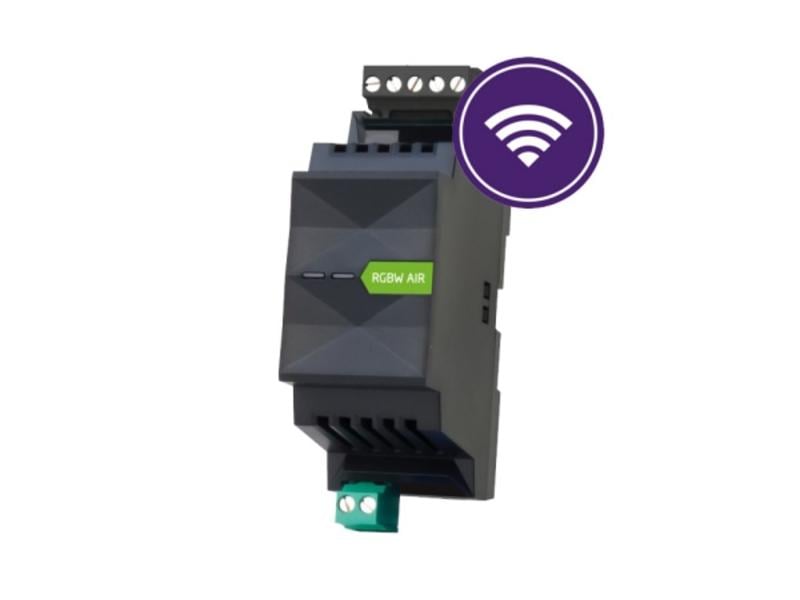
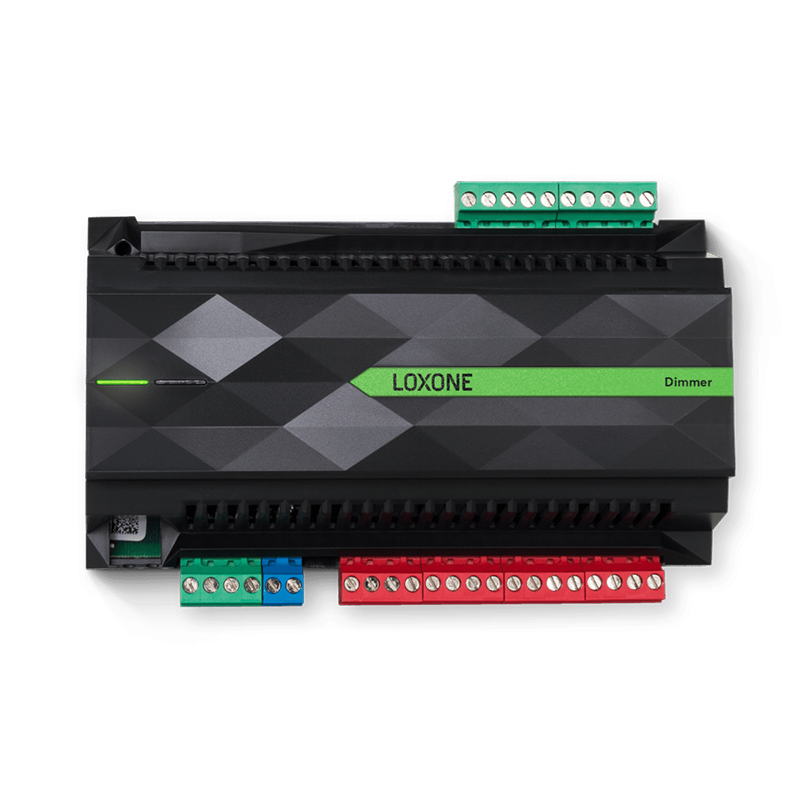
Standard for stage lighting technology. Wide range of dimmers and components available. Standard: 512 channels (Loxone restriction: 128 channels) RGBW dimmer for Loxone Tree is under development (December 2016). There is only one device, the Loxone Dimmer Extension. Maximum number of Loxone extensions is not defined. Given the limited number of analog outputs is not suitable for larger installations.


 0 kommentar(er)
